After some months without opening Twitter at all, I decided get some inspiration and explore new techniques late in 2022. That's when
I saw a post mentioning a new edition of
Genuary, a month dedicated to Generative Art with the Twitter community.
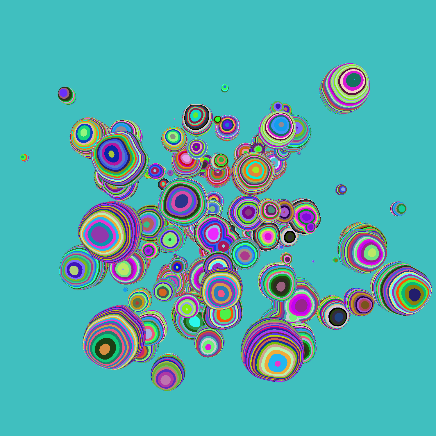
The principle is simple: every day of January, you can create a visual guided by different prompts. For instance, the
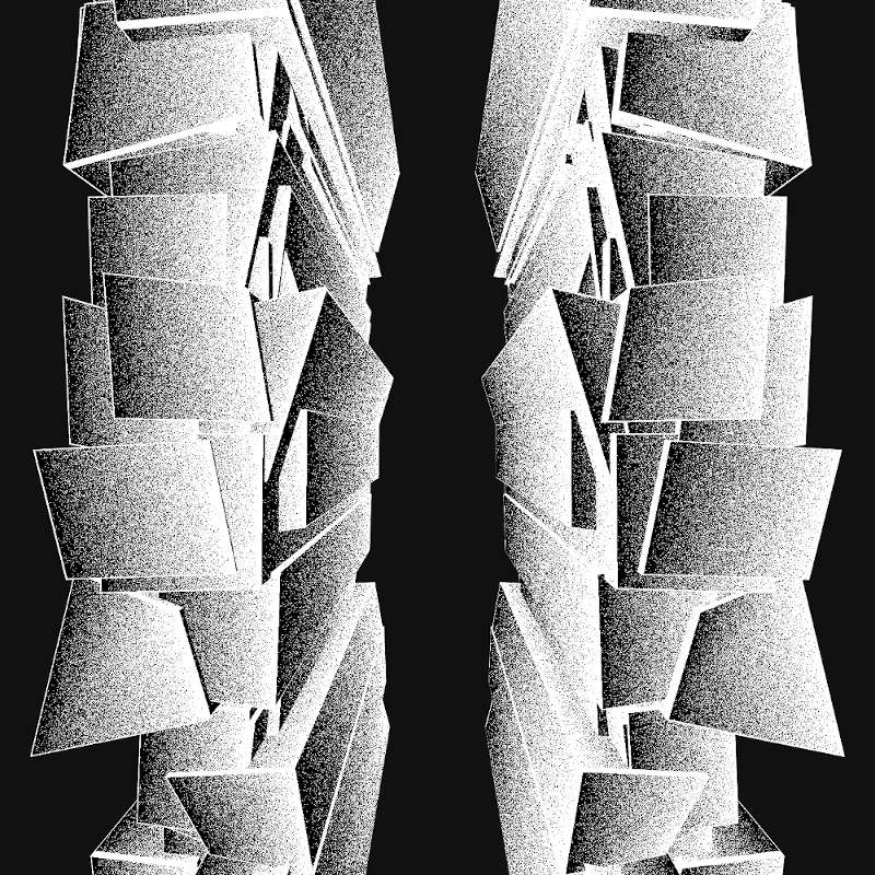
picture you see above is for January 29th and the prompt is Maximalism. Nobody rates anything, and we are as free as
we want to create a generative art piece every day. You post your creation and get inspiration from many others. In a later post, I will explain what I learnt from a creative perspective
-following some constraints to increase creativity. But in this post,
I will share some new techniques I learnt. Sharing and learning.
For the occasion, I created a website with all my entries, and published
my source code for every prompt. Below are some techniques I learnt (among others)
and some words about their implementation.
SVG, Three.js and shaders combinedAll my entries and techniques use Three.js and/or GLSL. Understanding the brief descriptions
might require some prior knowledge with these technologies.
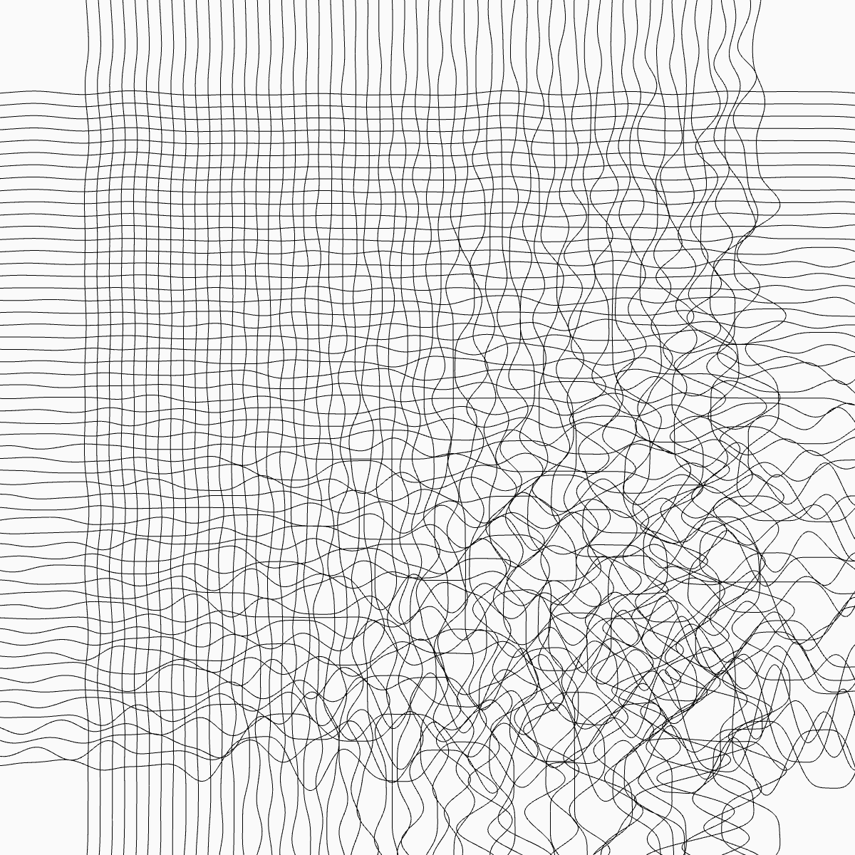
1. Randomizing on demand
Most of my entries include a randomizer: the user can click to generate a new entry of the piece. This way, a set of rules creates a unique piece at any time for any user.
In the above example (live), every time the page is refreshed or the "Randomize" button is clicked, a new seed is created. This
seed is then used in the code to create the unique piece. To call a new seed, I generally create it with Math.random() which generates
the random key and then use it to generate colors, positions etc.
If my meshes are built with a shader material, I pass the seed as a uniform and use it in my fragment and vertex shader:
// In my init() function with Three.js
const uniforms = {
  u_time: { value: 0 },
  u_seed: { value: Math.random() }
}
// In my fragment shader
color = mix(
  color,
  vec3(random(vec2(u_seed)), random(vec2(u_seed)), random(vec2(u_seed)) ),
  box(st, vec2(0.3))
);
Every time the
init() is called, the fragment shader will get a new seed. Here, the seed is used to create a mix of the initial color with
a random shade of gray to draw a box.
2. Camera or Mesh following a path
In two entries, I wanted a mesh or the camera to follow a path. For Entry #9: Plants,
the camera is moving from one point to another via an interpolation. For Entry #26: My Kid Could Have Done It,
the paper plane is following a path. To realize the latest, I stuck to an official
Three.js example where the camera is moving along a spline.
I recommend to start there if you'd like to implement such effect. Basically, you have to (1) create a spline, (2) create a mesh as a Tube Geometry
out of it and (3) make your object follow the path in your render() function. The last point can be tricky and
I stuck with the official example to have the proper interpolation, direction and lookAt.
// (1) creating the Spline
const sampleClosedSpline = new THREE.CatmullRomCurve3(pointsForSpline); // pointsForSpline being an array of points which will be interpolated
sampleClosedSpline.curveType = 'catmullrom';
sampleClosedSpline.closed = true;
// (2) create a mesh as a Tube Geometry
geometrySpline = new THREE.TubeGeometry( sampleClosedSpline, 3000, 2, 8, true );
meshSpline = new THREE.Mesh( geometrySpline, materialSpline );
// (3) make your object follow the path
// define the time a loop takes and its increment, t
const looptime = 30 * 1000;
const t = ( time % looptime ) / looptime;

// get the position (our t, between 0 and 1) on the curve according to the arc length
geometrySpline.parameters.path.getPointAt( t, position );
position.multiplyScalar( scalar );

// compute one point and the next one for interpolation
const segments = geometrySpline.tangents.length;
const pickt = t * segments;
const pick = Math.floor( pickt );
const pickNext = ( pick + 1 ) % segments;

// calculate the directions with normals
binormal.subVectors( geometrySpline.binormals[ pickNext ], geometrySpline.binormals[ pick ] );
binormal.multiplyScalar( pickt - pick ).add( geometrySpline.binormals[ pick ] );
geometrySpline.parameters.path.getTangentAt( t, direction );
const offset = -5;

normal.copy( binormal ).cross( direction );
position.add( normal.clone().multiplyScalar( offset ) );

geometrySpline.parameters.path.getPointAt( ( t + 30 / geometrySpline.parameters.path.getLength() ) % 1, lookAt );
lookAt.multiplyScalar( scalar );
lookAt.copy( position ).add( direction );

// position and lookAt of the mesh are updated
meshPlane.position.copy( position );
meshPlane.matrix.lookAt( meshPlane.position, lookAt, normal ); // angle of the mesh is updated
meshPlane.quaternion.setFromRotationMatrix( meshPlane.matrix );
}
3. SVG, Three.js and Shaders combined

In various entries, including the one above, I wanted to distort an SVG file with shaders. The steps are made quite easy with
Three.js. First, you load the SVG with the SVGLoader() and then you apply a ShaderMaterial to it.
To distort my shapes, I generally add noise to my Vertex Shader so that my original SVG path is distorted.
// creating a ShaderMaterial
const material = new THREE.ShaderMaterial({
  vertexShader,
  fragmentShader,
  uniforms: uniforms
})
// loading my SVG path
const url = '/svg/cenizas.svg';
const loader = new SVGLoader();
loader.load( url, function ( data ) {
  const paths = data.paths;
  for ( let i = 0; i < paths.length; i ++ ) {
    const path = paths[ i ];
    for ( let j = 0, jl = path.subPaths.length; j < jl; j ++ ) {
      const subPath = path.subPaths[ j ];
      const geometry = SVGLoader.pointsToStroke( subPath.getPoints(), path.userData.style );
      if ( geometry ) {
        mesh = new THREE.Mesh( geometry, material ); // <-- applying the shader material
      }
    }
  }
})
// Adding noise in the Vertex Shader
void main () {
pos = position;
pos.x += noise(pos.xy * 0.08 + u_time * 4.) * pow(sin(u_time), 2.);
pos.y += noise(pos.xy * 0.08 + u_time * 4.) * pow(sin(u_time), 2.);
gl_Position = projectionMatrix * modelViewMatrix * vec4(pos, 1.0);
}
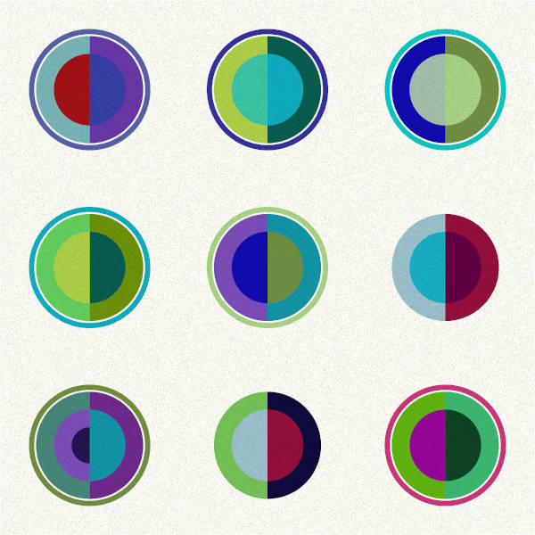
4. Signed Distance Functions
Signed Distance Functions (SDFs) were the name of the prompt for day #8. I was new to it, as for many participants.
The prompts were coming with some guidance, and I stuck to one
youtube video by
Sebastian Lague that explains the concept really well and two of the many articles about shaders by
Inigo Quilez. His website is a gold mine
for anyone new to shaders. As I wanted to design a 2D SDF (concept exists in 3D), I found the function in a first article:
2D Distance Functions and apply
the "blobby" effect thanks to a smooth minimum, described in a seconde article
Smooth Minimum - 2013. Old but unchanged, well explained,
and with code snippets.
I came up with a
first version on Shadertoy (code below). The way I was seeing it in the end was
a function to compute a distance between a geometry and a point (or other geometry). "Signed" because the distance is positive if the
point is outside of the geometry and negative if it is inside. In my example, I'm using the SDF to make a union of the shapes (the same way, you could get the intersection)
and I am using the smooth minimum to make the union "softer" on the borders of my circles.
float sdCircle( in vec2 p, in float r ) {
return length(p)-r;
}
float smin(float a, float b, float k) {
float h = max(k - abs(a-b), 0.) / k;
return min(a, b) - h*h*h*k*1./6.;
}
void mainImage( out vec4 fragColor, in vec2 fragCoord ) {
float pix = 2./iResolution.y;
vec2 p = (2.*fragCoord-iResolution.xy)/iResolution.y;
vec2 m = (2.*fragCoord-iResolution.xy)/iResolution.y;
float f = 0.9;
float d = sdCircle(p,0.8);
float dd = sdCircle(m+vec2(sin(iTime*f + 1.)*1.5,sin(iTime*f + 1.)*0.4),0.2);
vec3 col = vec3(1.);
col = mix(col, vec3(0.), smoothstep(-pix,pix, smin(d,dd,1.0) - .0375 ));
col = mix(col, vec3(0.), smoothstep(pix,-pix, smin(d,dd,0.3) - .0065 ));
fragColor = vec4(1.-col,1.0);
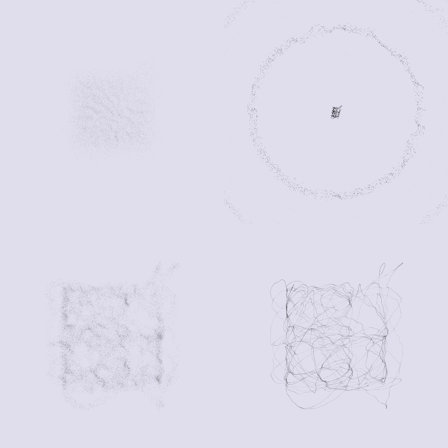
}5. Instancing mesh with shader material
The last technique I wanted to describe here is about instancing in Three.js and its impacts on your shader material.
When I started to code in Three.js, I was ignoring the instancing part. If you are new, you might be doing the same. Basically,
you create your geometries and meshes one by one, or in a loop, and stick with this pattern in your render() function. Each mesh will require a "draw call". It didn't take
long before I realized how bad the performance were with this pattern when drawing thousands of shapes.
From there, I started to use instancing. Instead of creating as many meshes and geometries as you want to see, you create only one geometry and duplicate
all its vertices. You can loop over the vertices to give them specific attributes (color, positions or custom attributes) and
get the look you were looking for (10,000 cubes for instance) with only one "draw call". This
article by Dusan Bosnjak explains what is behind it
in WEBGL.
With this in mind, I was wondering how to apply a shader to my mesh as a whole, and to my individual shapes.
First, in your vertex shader, you have to specify you are in an "instance mode". Currently, this part is explained in the very last
documentation link, "WebGL Renderer":
// Note that modelViewMatrix is not set when rendering an instanced model,
// but can be calculated from viewMatrix * modelMatrix.
// Basic Usage:
gl_Position = projectionMatrix * viewMatrix * modelMatrix * instanceMatrix * vec4(position, 1.0);gl_Position = projectionMatrix * viewMatrix * modelMatrix * vec4( position, 1.0 );// Entry #1: getting gl_Position.z (world Z position) to create a fog effet
// and sticking with vUv to colorize each individual the same way
varying vec2 vUv;
varying float posZ;
void main () {
gl_Position = projectionMatrix * viewMatrix * modelMatrix * instanceMatrix * vec4(position, 1.0);
vUv = uv;
posZ = gl_Position.z;
}// Entry #29: getting "pos", the position dependent on the InstanceMatrix
// to colorize each individual in a different way
void main () {
vUv = uv;
pos = (instanceMatrix * vec4(position, 1.0)).xyz;
vec3 ver = position;
ver.x += noise(pos.xy/20. + u_time/2.) * 4.;
ver.y += noise(pos.xy/20. + u_time/2.) * 4.;
gl_Position = projectionMatrix * viewMatrix * modelMatrix * instanceMatrix * vec4(ver, 1.0);
}6. Some other techniques learnt
Finally, I will list some other techniques I learnt on the way. Some may be new topics for other articles.
All 31 entries were good opportunities to learn. Sometimes, the time to learn takes over the time to get a satisfying output but I will dig into some techniques to create collections of pieces that I will showcase in the blog. Thanks for reading this far!